
In this article I would like to explore DHCP requests so that we can understand what happens when a device sends a request to a DHCP server.
Lets start by listing some important information about DHCP…..
- DHCP is the abbreviation for Dynamic Host Configuration Protocol
- DHCP uses UDP 67 & 68 – 67 – In a client-server environment port 67 is the BOOTP for the DHCP server and 68 is the BOOTP for the client
- The purpose of DHCP is to assign IP addresses automatically to the device that has requested an IP address
How does the client interact with the DHCP server?
In short…
- The client sends a DISCOVER frame asking for an IP address
- The DHCP server responds with an OFFER which contains an IP address and additional information
- The client sends a REQUEST to use the IP address contained in the OFFER
- The DHCP server ACKNOWLEDGES the request to use the IP address
The above process is what happens on the surface however there is a lot more going on if we take a look at the frames using Wireshark.
Behind the scenes of a DHCP request…
Below is the topology we are going to work from to explain the DHCP process in depth.
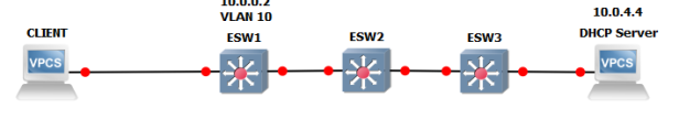
Image .1
The client on the left doesn’t have an IP address yet and would like to request one from the DHCP server located at 10.0.4.4. The switches are configured with ip helper-addresses to relay DHCP information. ESW1 has a VLAN 10 static IP address of 10.0.0.2. The ip helper-address and ESW1 IP address are only relevant so I can explain the Wireshark capture pictured below.

Image.2
We have a lot of detail to cover so I will break each frame down using the numbers (No.) in the above image and then within those numbers we will examine the information further.
Frame Number 383.
This is the first frame sent by the client when requesting an IP address automatically. On the surface of image .2 we can see that the source IP address is 0.0.0.0, the destination IP address is 255.255.255.255, the protocol is DHCP and in the info we can see that it is a DHCP Discover message.
The reason the client has a source IP address of 0.0.0.0 is because it doesn’t currently have a layer 3 address. The client doesn’t know the IP address of the DHCP server so it sends the frame with a destination IP address of 255.255.255.255 which is a broadcast address.
If we look at image .3 below, we start by examining the Layer 2 information. As with the client not knowing the destination IP address, it also doesn’t know the destination MAC address so it too sets the destination MAC address to a broadcast of ff:ff:ff:ff:ff:ff.
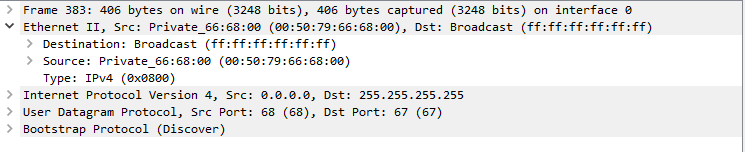
Image .3
If we now take a look at the Layer 3 information in Image .4 we can see that the source IP address is set to 0.0.0.0 and this is because the client doesn’t currently have an I P address. The destination address is set to 255.255.255.255 and this is because the client doesn’t know the destination address of the DHCP server so it sends it to the broadcast L3 address.
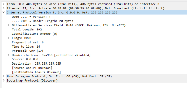
Image .4
If we take a look at the protocol and port information in Image.5 we can see the source port that the DHCP Request has originated, Port 68. The destination port is that of a DHCP server and the protocol is UDP which is connection-less.
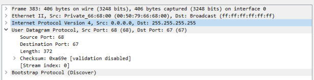
Image .5
The last field in the Discover frame is the Bootstrap protocol. The BOOTP protocol is defined in RFC 951 as a protocol that assigns IP addresses and other information to networking devices.
If we look at the BOOTP fields in Image .6 we can see much of the information we have already identified along with option fields. In option (12) we can see that the client has been identified as SALES1. Much of this information will change in the frames we examine later on.
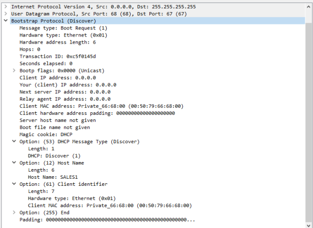
Image .6
This concludes Frame number 383 which was the DHCP Discover frame, we will now move onto the DHCP Offer packet number 385.
For Packet number 385 I have missed out the Layer 1 and Layer 2 information as there isn’t anything particular interesting to explore. In Image 7. we start with the Layer 3 information and we can see the original source IP address of the ESW1 switch. If we look at the Destination IP address, you will see 10.0.0.51, this IP address is the one being offered to the client by the DHCP server.
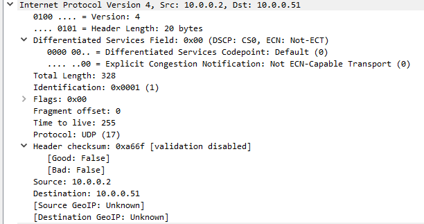
Image .7
Moving onto the Layer 4 information in Image .8 we can see some UDP information that is worth explaining. As the DHCP Offer is flowing back to the client PC from the server we can see that the Source port is 67 and the Destination port is 68. All we need to know about these two port numbers is that 67 is the bootstrap protocol (BOOTP) from the server and 68 is the bootstrap protocol (BOOTP) for the client.
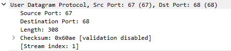
Image .8
Image .9 shows some very interesting information about the DHCP offer packet. If we look at the ‘Client IP address’ field we can see that the client still doesn’t have an IP address until this packet reaches the client and requests to have the IP address of 10.0.0.51 shown in ‘Your (client) IP Address’ field.
The ‘Relay agent IP address’ field shows the IP address for the ESW1 switch as this is acting as the DHCP relay device.
Skipping over some of the details we can see the subnet mask of the host in ‘Option (1)’ , we also see further down some more options that include the renewal information, lease time and DHCP server identifier.
This concludes the inspection of the DHCP Offer packet 383, we will now have a look at what happens when the client receives the offer and chooses to accept the IP address.
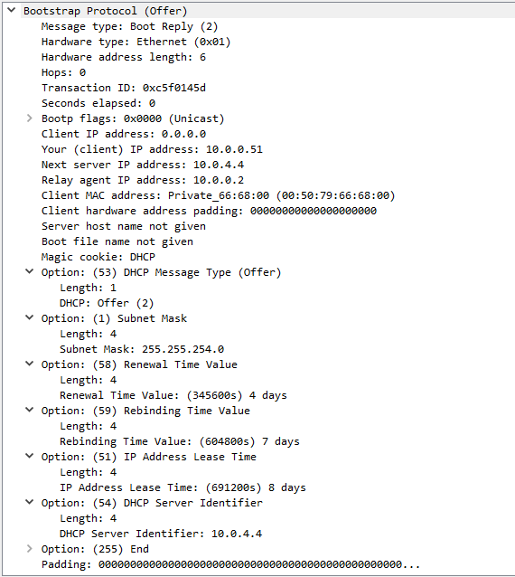
Image .9
So the client has now received the DHCP Offer and would like to accept the IP address 10.0.0.51 that the server offered. To do this the client first needs to respond to the server via the DHCP Request packet shown in Image.10.
If we look at the Layer 3 information we can see that the client still hasn’t been assigned the 10.0.0.51 IP Address, this is because it doesn’t happen until the server acknowledges the Request packet. So the request message is still sent in this case as a Broadcast message on the network with a destination IP address of 255.255.255.255.
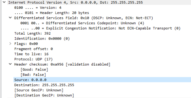
Image .10
Looking at the Layer 4 information in Image .11 we can see that the Source port is 68 and the Destination port is 67. As mentioned earlier in this post, these port numbers represent the BOOTP Client and BOOTP Server.
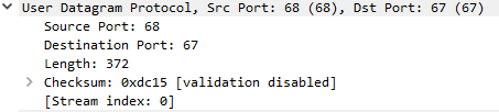
Image .11
Now this is where the inspection gets slightly more interesting with the DHCP Request packet. In Image .12 we can see that although the field ‘Next server IP Address’ shows the IP address of 0.0.0.0, further down in the options we see that the ‘DHCP Server Identifier’ shows the server address of 10.0.4.4. In ‘Option 50’ we see the requested IP address information that the client would like and further down we see the hostname of the client machine.
‘Option 55’ displays some additional information that the client would like to request, in this case we can see that the client would like the following:
- Subnet Mask
- Router (I believe this is the gateway information)
- DNS settings
- Domain name
All this information makes up the DHCP Request packet so now we will take a look at what happens when the server receives the request and what it does next.
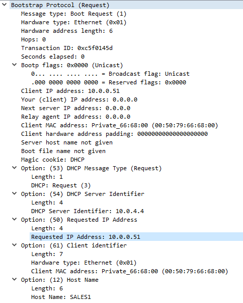
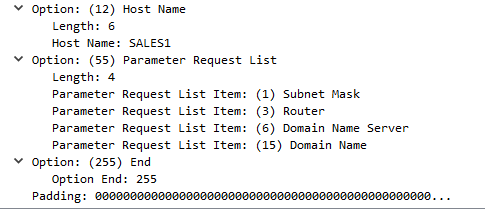
Image .12
So now that the server has received the DHCP Request we just talked about the server sends an Acknowledgement to the client as shown in Image .13. If we take a look at the Layer 3 information we can see that the server sends the Acknowledgment packet to ESW1 switch at 10.0.0.2 who will then forward onto the client.
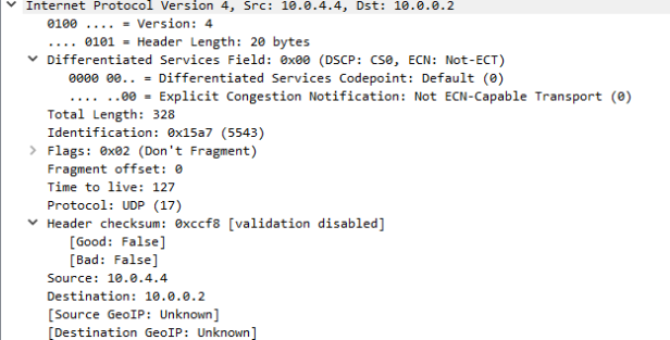
Image .13
The Layer 4 information in Image .14 shows that the source port and destination port is the same for the Acknowledgement packet and I believe this is because the server is just sending and ACK only.
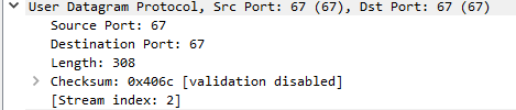
Image .14
If we look at the last section of the Acknowledgement packet we can see that the server has sent all the additional information the client requested in the last packet. Then the last image named Image .16 shows ESW1 forward the ACK packet onto the client. This then completes the DORA process and the assignment of the dynamic IP Address to the client is complete.
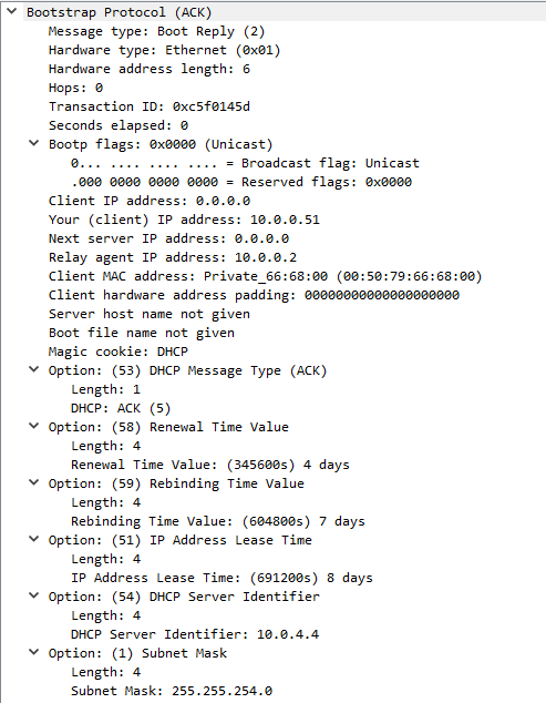
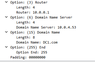
Image .15
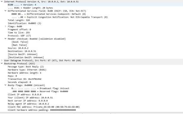
Image .16
I hope you have found this post useful, if you have any questions please drop us a comment.


Sweet keep it up. Nice article and easy to follow up. Thanks.
LikeLiked by 1 person
Thank you Hackaass 😉
LikeLike
Wow, marvelous blog structure! How lengthy have
you been running a blog for? you make running a blog look easy.
The overall look of your website is fantastic, as neatly
as the content!
LikeLike
Thank you 🙂
LikeLike
It’s a shame you don’t have a donate button! I’d definitely donate to
this brilliant blog! I suppose for now i’ll settle for book-marking and adding your RSS feed to my Google account.
I look forward to brand new updates and will share this website with my Facebook group.
Talk soon!
LikeLike
Hello Emily,
Thank you for wanting to donate and I am glad you like my blog. I don’t accept donations, I enjoy helping others and sharing my knowledge. I am glad you have shared my blog and I hope you enjoy the future content 🙂
LikeLike
Hi there! This post couldn’t be written any better!
Reading through this post reminds me of my previous roommate!
He always kept talking about this. I’ll send this post to him.
Pretty sure he will have a very good read. Thanks for sharing!
LikeLiked by 1 person
It is really a nice and helpful piece of info. Im glad that you shared this helpful information with us. Please keep us up to date like this. Thanks for sharing. cbkebdebkfkeekdk
LikeLiked by 1 person
Hello, I wish for to subscribe for this blog to obtain hottest updates, therefore where
can i do it please help out.
LikeLike
Hello, you can do so by navigating to the home page and entering your email in the subscription section on the left hand side.
Thanks
LikeLike