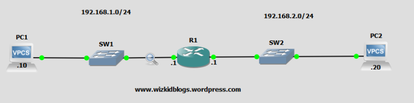
In this article I will explain demultiplexing and how it works by walking through a .pcap file taken from the lab in the screenshot below. We will focus on the data flowing from PC1 and SW1 to R1’s ingress port.
Demultiplexing (DEMUX) is the method in which the TCP/IP stack uses to determine if datagrams have been received correctly and if so, how should they be processed. Demultiplexing looks at certain fields at each layer of the TCP/IP stack, these fields include MAC addresses, IP addresses, protocols and ports. Checksums are also accounted for to verify the datagram hasn’t been damaged during transit.

Physical
I sent a DHCP request from PC1 into the network and captured the request on the Gigabyte interface connecting SW1 and R1, we will use the DISCOVER .pcap file to walk through demultiplexing. As shown in figure .1, the Ethernet frame enters the ingress interface of R1 from PC1. We have lots of information to accompany the datagram but our main focus is the Encapsulation type which in this case tells us its Ethernet.
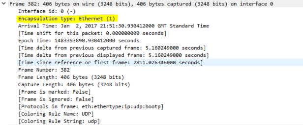
Figure .1
Data Link
The frame contains a 48-bit MAC Address of the destination and a 16-bit Ethernet type filed as shown in figure .2. As this is a DHCP request, the destination MAC-Address is the broadcast address of ff:ff:ff:ff:ff:ff. As the router is not configured as a DHCP server and no helper address is configured, the router will eventually drop the packet after realising what application it is trying to reach, but before it does just that, the datagram is processed further.
The 16-bit Ethernet type is used to identify what upper layer (Layer 3) protocol the datagram contains, in this case we have an IPv4 datagram. The HEX value of 0x0800 indicates that it is an IPv4 datagram, other options include:
Address Resolution Protocol (ARP) – 0x0806
Internet Protocol version 6 (IPv6) – 0x86DD
Once this frame has been checked for errors (checksum) the frame is stripped of the header and trailer and then the IP datagram is then passed onto the network layer for further processing.
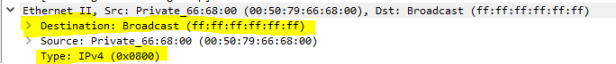
Figure .2
Network
Now that the IP datagram has reached the network layer, the destination IP addressed is examined. As the destination network is the broadcast address of 255.255.255.255 as shown in figure .3 the router will not forward this broadcast because we don’t have a relay configured. But suppose the packet was destined for this router, after checking the destination IP address it would move onto demultiplexing the protocol field which in this case is UDP (17). Other values include:
Internet Control Message Protocol – ICMP (1)
Internet Group Management Protocol – IGMP (2)
Internet Protocol version 4 – IPv4 (4)
Transmission Control Protocol – TCP (6)
If required, any data that is fragmented will be reassembled before the transport layer is analysed.
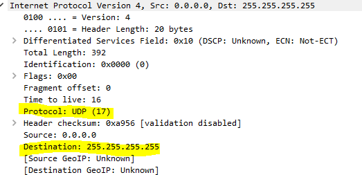
Figure .3
Transport
Once the packet has reached the transport layer the destination port number as depicted in figure .4 is used for demultiplexing to the appropriate application.
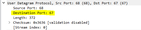
Figure .4

